If the calling unit receives an add-on number that is longer than the number it initially dialed, it discards extra digits it receives for add-on numbers starting with the leftmost digit. It the add-on number is shorter than the dialed number, the calling unit adds on the rightmost digits of the initially dialed number. (For example, if 6532 is the add-on number, and 9-555-6588 is the initially dialed number, the derived phone number is 9-555-6532.)
For example, if each channel of four T1 lines is assigned a different phone number, you have 96 phone number assignments. Typically, those numbers have leading digits in common, for example:
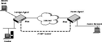
An ATMP session occurs between two MAX units via UDP/IP. All packets passing through the tunnel are encapsulated in standard GRE (Generic Routing Encapsulation) as described in RFC 1701. ATMP creates and tears down a cross-Internet tunnel between the two MAX units. In effect, the tunnel collapses the Internet cloud and provides what looks like direct access to a home network. Bridging is not supported through the tunnels. All packets must be routed using IP or IPX.
One of the ATMP MAX units acts as a "foreign" agent (typically a local ISP) and one as a "home" agent (which can access the home network). A mobile node dials into the foreign agent, which establishes a cross-Internet IP connection to the home agent. The foreign agent then requests an ATMP tunnel on top of the IP connection. The foreign agent must use RADIUS to authenticate mobile nodes dial-ins.
The home agent is the terminating part of the tunnel, where most of the ATMP intelligence takes place. It must be able to communicate with the home network (the destination network for mobile nodes) through a direct connection, another router, or across a nailed connection.
For example, in Figure 3, the mobile node might be a sales person who logs into an ISP to access his or her home network. The ISP is the foreign agent. The home agent has access to the home network.
You can specify the IP address of one or two BOOTP servers. You are not required to specify a second BOOTP server.
Note: If you specify two BOOTP servers, the MAX that relays the BOOTP request determines when each server is used. The order of the BOOTP servers in the BOOTP Relay menu does not necessarily determine which server is tried first.
Combinet
Combinet connections bridge to remote Combinet LANs. Combinet connections support password authentication using Combinet authentication. They can be dial-in or dial-out switched connections and can use two channels (128 kbps). Connections
The MAX creates connections based on a combination of profiles: Answer profile
The Answer profile determines whether an incoming call is answered or dropped. If the call doesn't comply with the Answer profile, the MAX drops the call before answering it. User profiles
User profiles provide simple name/password authentication for incoming calls. They are used only if authentication is required in the Answer Options > Authentication tab. If authentication is required for inbound calls, the MAX prompts dial-in users for a name and password. If the name and password the user enters matches a User profile, the MAX accepts the call and uses the settings in the Answer profile or a specified Connection profile to build the connection. Connection profiles
Connection profiles define individual connections. For a given encapsulation type, the Connection profile contains many of the same options as the Answer profile. You can also use a Connection profile as a template to create a conneciton in conjunction with User profiles. RADIUS user profiles
If you are using RADIUS, you can create User profiles for each conneciton. A User profile consists of a series of RADIUS attributes that specify a username and password, and enable you to configure routing, bridging, call management, and restrictions on the types of MAX resources a caller can access. Control monitor
The Control Monitor is a menu-based user interface for configuring, managing, and monitoring the MAX. It consists of nine windows-eight status windows and a single edit window. Refer to your MAX documentation for information on using the Control Monitor interface. CSU (Channel Service Unit)
A CSU is a network interface unit. You use a CSU to connect your MAX to the local digital telephone system. You use a DSU to connect the CSU to your MAX if the MAX does not have an internal CSU. DCE (Data Circuit-Terminating Equipment)
As defined in the RS-232 specification, equipment to which DTE (Data Terminal Equipment) is connected, often to enable access to network facilities. A DCE converts the format of the data coming from the DTE into a signal suitable to the communications channel. DCE often refers to equipment such as network access equipment, and DTE refers to application equipment, such as a videoconference terminal.
DHCP (Dynamic Host Configuration Protocol)
DHCP, described in RFC 1531 is a standards-based protocol for dynamically allocating and managing IP addresses. DHCP runs between individual computers and a DHCP server to allocate and assign IP addresses to the computers as well as limit the time for which the computer can use the address. When the time expires on the use of the IP address, the computer must contact the DHCP server again to obtain an address. Digital modem
A digital modem is a device that can communicate over a digital line (such as an ISDN line) with a station that uses a modem connected to an analog line. Incoming modem calls and incoming digital calls come over the same digital line to the MAX unit's integrated digital modem. The MAX can also make an outgoing call over a digital line to a modem on an analog line. DNS (Domain Name System)
DNS is a TCP/IP service that enables you to specify a symbolic name instead of an IP address. A symbolic name consists of a username and a domain name using the format username@domain name. The username corresponds to the host number in the IP address; the domain name corresponds to the network number in the IP address. A symbolic name might be steve@abc.com or joanne@xyz.edu. Drop and Insert
Drop-and-Insert is a feature that enables a single T1 access line to carry both data and voice traffic. The MAX uses a pre-allocated portion of the T1 access line to use both nailed-up and switched circuits for LAN internetworking. The remaining portion of the line goes to a PBX (Private Branch Exchange) with a T1 interface; the PBX can access both nailed-up and switched circuits for voice purposes. DSU (Data Service Unit)
A digital service unit that converts terminal interfaces such as RS-232 connections to DSX-1 interfaces. Increasingly, the functions of these DSUs are incorporated into sophisticated remote access devices located at the central site. DTE (Data Terminal Equipment)
As defined in the RS-232 specification, equipment to which DCE (Data Circuit-Terminating Equipment) is connected, such as personal computers or data terminals. DTE often refers to application equipment, such as a videoconference terminal or LAN bridge or router, while DCE refers to equipment such as network access equipment.
Dynamic Bandwidth Allocation (DBA)
DBA is a way to automatically add or subtract channels "on demand." When traffic levels expand, the MAX adds switched channels to the call. When traffic levels subside, it removes the channels and frees up the bandwidth for re-allocation. To add a channel, the MAX dials (or answers) another call. Both the local and far-end DBA calculations can result in additional channels being added to the connection. If the two sides of a connection disagree on the number of channels needed for a connection, the side requesting the greater number prevails. Calculations on the required number of channels are made by each side based on the traffic received at that side. Fractional T1
A fractional T1 circuit is a nailed-up connection to a T1 line with a bandwidth that might be only a fraction of the full T1 bandwidth. Frame Relay
Frame Relay is a High Level Data Link Control (HDLC)-based packet protocol that enables you to send data to a destination using one or more frame relay switches within a private network or a public carrier's network. For further information see Hunt group
A group of channels that share the same phone number is called a hunt group. When a call comes in using the phone number assigned to the hunt group, the switch hunts for an available channel in the group. Inband signalling
For inband signaling, the line uses 8 kbps of each 64-kbps channel for WAN synchronization and signaling; the remaining 56 kbps handle the transmission of user data. T1 access lines containing one or more switched channels, and Switched-56 lines use inband signaling. Incoming call routing
If the incoming call is a voice call and your system has at least one digital modem, the MAX assigns the call to the first available digital modem. If no digital modems are available, the MAX rejects the call. If no digital modems are installed, the MAX treats the call as a data call.
If the call is an asynchronous V.110 call, the MAX routes the call to the first available V.110 port. If no V.110 ports are available or installed, the MAX rejects the call.
A serial host port is the V.35, RS-499, or X.21 port on the MAX. If the MAX finds a serial host port that can accept an incoming call, the MAX routes the call to the host port. If the MAX does not support host ports, it skips this step.
Class |
Address range |
Network bits |
|---|---|---|
|
Class A
|
0.0.0.0 --127.255.255.255
|
8
|
|
Class B
|
128.0.0.0 --191.255.255.255
|
16
|
|
Class C
|
192.0.0.0 -- 223.255.255.255
|
24
|
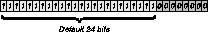
ip-address = 198.5.248.40/29In the example address shown above, the /29 specification indicates that 29 bits of the address will be used to specify the network. This is commonly referred to as a 29-bit subnet. The three remaining bits are used to specify unique hosts.
Eight bit-combinations are possible in 3 bits. Of those 8 possible host addresses, 2 are reserved:
000 - Reserved for the network (base address)
Note: Early implementations of TCP/IP did not allow zero subnets. That is, subnets could have the same base address that a class A, B, or C network would have. For example, the subnet 192.168.8.0/30 was illegal because it had the same base address as the class C network 192.168.8.0/24, while 192.168.8.4/30 was legal. (192.168.8.0/30 is called a zero subnet, because like a class C base address, its last octet is zero.) Modern implementations of TCP/IP allow subnets to have base addresses that might be identical to the class A, B, or C base addresses. Ascend's implementations of RIP 2 and OSPF treat these so-called zero subnetworks the same as any other network. However, it is important that you treat zero subnets consistently throughout your network. Otherwise, you will encounter routing problems!
Table 7 shows how the standard subnet address format relates to Ascend notation for a class C network number.
198.5.248.120/29The Ethernet attached to that router has the following address range:
198.5.248.120 - 198.5.248.127Note: A host route is a special case IP address with a subnet mask of /32; for example, 198.5.248.40/32. Host routes are required for a dial-in host.
To communicate with multicast clients, the MAX sends the clients IGMP queries every 60 seconds, receives responses, and forwards multicast traffic. To the clients it looks like a multicast router, although in fact the MAX is forwarding multicast packets based on group memberships. In this implementation, multicast clients are not allowed to source multicast packets-if they do, the MAX discards the packets.
When the MAX creates a new group membership, it sends a JOIN message on its MBONE interface. When the last member of a group is no longer active, if the MBONE interface supports a multicast router running IGMP, the MAX sends a LEAVE message.
To communicate with an MBONE router, the MAX acts as a multicast client-it receives queries from the router and responds to them using IGMP. The multicast (MBONE) router may reside on its Ethernet interface or across a WAN link. If the router is accessed across the WAN, the MAX may respond to multicast clients on its Ethernet interface as well as across WAN links.
Because the supply of addresses is rapidly diminishing a company may not be able to get official addresses for their entire network. Other sites may already be configured with unofficial addresses, but now want access to the Internet, where an official address is required. For these reasons, when routing to the Internet, a facility to borrow an official address and dynamically translate between the local and official addresses is necessary.
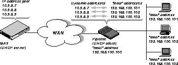
The Pipeline acts as a DHCP client on behalf of all hosts on the LAN and relies on the MAX unit (acting as the DHCP server) to provide addresses suitable for the remote network from its IP address pool. On the local network, the Pipeline and the hosts all have "local" addresses on the same network that are only used for local communication between the hosts and the Pipeline over the Ethernet.
When the first client on the LAN requests access to the remote network, the Pipeline gets this address through PPP negotiation. When subsequent clients request access to the remote network, the Pipeline asks for an IP address from the MAX using a DHCP request packet. The MAX then sends an address to the Pipeline from its IP address pool. The Pipeline uses the dynamic addresses it receives from the MAX to translate IP addresses on behalf of local clients.
As packets are received on the LAN, the Pipeline determines if the source IP address has been assigned a translated address. If so, then the packet is translated, and forwarded out the WAN. If no translation has been assigned (and is not pending), then a new DHCP request is issued for this IP address. While waiting for an IP address to be offered by the MAX, corresponding source packets will be dropped. Similarly, for packets received from the WAN, the Pipeline checks the destination address against its table of translated addresses. If the destination address exists and is active, the Pipeline forwards the packet. If the destination address does not exit, or is not active, the packet is dropped.
IP addresses are typically offered by the MAX only for a limited duration, but the Pipeline automatically renews the lease on these addresses. If the connection to the remote server is dropped, all leased addresses are considered revoked. Therefore, TCP connections will not persist across calls.
Figure 8 illustrates a basic NAT for LAN set up.
Note that the Pipeline itself does not have an address on the remote network. This means that the Pipeline can only be accessed from the local network, not from the WAN.
In some installations, the MAX will be handling both NAT DHCP requests and ordinary DHCP requests. In this situation, if the ordinary DHCP clients are connecting to the MAX over a non-bridged connection, you must have a separate DHCP server to handle the ordinary DHCP requests; the MAX will only handle the NAT DHCP requests.
Note: The most common reason multi-channel calls fail to connect beyond the initial connection is that the answering unit sends the calling unit phone numbers it cannot use to dial the other channels. The first rule to follow to avoid this problem is to make sure that the phone numbers you assign have the same number of digits. If the calling unit receives an add-on number that is the same length as the number that established the base channel of the call, the entire add-on number is used. (For example, if 6532 is the add-on number, and 6588 is the initially dialed number, the derived phone number is 6532.)
If the calling unit receives an add-on number that is longer than the number it initially dialed, it discards extra digits it receives for add-on numbers starting with the leftmost digit. It the add-on number is shorter than the dialed number, the calling unit adds on the rightmost digits of the initially dialed number. (For example, if 6532 is the add-on number, and 9-555-6588 is the initially dialed number, the derived phone number is 9-555-6532.)
For example, if each channel of four T1 lines is assigned a different phone number, you have 96 phone number assignments. Typically, those numbers have leading digits in common, for example:
Note: If all of a line's channels are assigned the same add-on number, you can leave the phone number assignment blank.
PPP is a single-channel connection that connects to any other device running PPP. MP and MP+ are enhancements to PPP for supporting multi-channel links. If a connection is set up for "MPP," the MAX first requests MP+. If the other side of the connection doesn't support MP+, the MAX requests MP. If that protocol is also refused, PPP is used instead. That is why the term "PPP connection" is often used to mean any one of these encapsulation methods when the number of channels is not relevant.
PPP connections support password authentication using PAP or CHAP, and can support IP routing, IPX routing, or protocol-independent bridged connections. They can be dial-in or dial-out switched connections.
A RADIUS server supports both PAP (Password Authentication Protocol) and CHAP (Challenge Handshake Authentication Protocol). PAP and CHAP are both PPP authentication protocols. CHAP is the more secure.
A serial host port uses pins for controlling the data flow through the port. A device sends a signal through a pin and over the line to another device; the signal being sent determines the control-line state. For example, a device can send a signal to another party, indicating that it has data to send; in this case, the control-line state is RTS (Request to Send). The other device can send a signal to indicate that it is ready to receive data; in this case, the control-line state is DTR (Data Transmit Ready). The process of sending these synchronization signals between serial host ports is called handshaking.
Note: When you install a serial host port card in the MAX, the serial host ports become the default route for inbound data calls, taking precedence over the bridge/router software. This means you must specify call routing for calls to reach the local Ethernet. See Incoming call routing for more information.
Serial WAN port
The MAX serial WAN port provides a V.35/RS-449 WAN interface that is typically used to connect to the DCE port of a frame relay switch or to another router. The serial WAN data rate is determined by the clock speed received from the link. The maximum acceptable clock is 8 Mbit/s. The clock speed at the serial WAN port has no effect on the bandwidth of other WAN interfaces in the MAX. Slot
A slot is an expansion slot on the back panel of the MAX. A port is an individual modem, V.110, or serial host port on an expansion card in one of those slots. Slot numbers
Slot numbering is used for configuring inbound and outbound call routing. The MAX unit's slots are assigned as follows:
For the MAX with built-in Ethernet, this menu is not applicable.
A trap is a mechanism in SNMP for reporting system change in real time. To report system change, the MAX sends a traps-PDU across the Ethernet interface to the SNMP manager. A complete list specifying the events that cause the MAX to send a traps-PDU appears in the Ascend Enterprise Traps MIB.
Note: Not all telephone companies include a suffix on their SPIDs. When receiving SPIDs from your telephone company, ask them to verify whether or not suffixes are included. The SPID formats described in the next sections have been agreed upon by most telephone companies.
For example, for an AT&T switch in multipoint mode, SPIDs have one of these formats:
01nnnnnnn0
01nnnnnnn00
In the AT&T SPID formats, nnnnnn is the 7-digit phone number (not including the area code). For example, if the phone number is 555-1212, the SPID will be 0155512120 or 01555121200.
For a Northern Telecom switch, SPIDs have one of these formats:
aaannnnnnnSS
aaannnnnnnSS00
In the Northern Telecom SPID formats, aaannnnnn is the 10-digit phone number (including the area code). SS is an optional suffix-if specified it is a one or two-digit number differentiating the channels. For example, if the phone numbers are 212-555-1212 and 212-555-1213, the SPIDs may be:
21255512121
21255512132
or:
212555121201
212555121302
or one of the above formats followed by 00 (for example, 21255512130200).
There is no "master" MAX unit in a stack. A MAX can become a member of a stack or leave a stack at any time, though there is no requirement that the MAX join a stack. The MAX units that are in the stack find each other by using an Ethernet multicast packet. Since these multicast packets are unlikely to cross a router, and because of the high traffic demands created by a MP/MP+ call that spans MAX units, all members of a stack must reside on the same physical LAN.
Once a stack is created every MP/MP+ call that comes into a member of the stack will be compared with MP/MP+ calls on other members of the stack. This is done to determine if the call is part of an already existing bundle. If this call is a new MP/MP+ bundle then it will proceed as normal. If the call is part of an already existing bundle then information about the bundle will be exchanged between the two MAX units.
The MAX that has answered the subsequent call will forward all data packets, via the Ethernet, to the MAX that owns the MP/MP+ bundle. Data packets destined for the WAN will be split between the available channels normally. Those packets that are destined for a WAN interface that is not local to the MAX that owns the bundle will be forwarded, via the Ethernet, to the appropriate MAX to be sent across the WAN link.
In the case of an MP+ call that must add a subsequent channel to an existing bundle the MAX must provide a phone number. In the case of a MAX stack the MAX that owns the bundle will attempt to provide a local phone number. If no phone number is available then the MAX will ask other members of the stack for an available phone number to use for the subsequent channel.
Note that call spanning works only with incoming calls. If a MAX wants to place another call but has no available lines a stack will not help. A stack is only effective when a MAX running MP+ is asked for another phone number and has no available lines, or when a rotary is used to access multiple MAX units via the same phone number, thus making it impossible to guarantee that a subsequent call is answered by the same MAX as the original call.
Note: A stack cannot share Connection profiles between MAX units. This means that all MAX units in a stack must contain all authentication information for every call or all MAX units in a stack must use a centralized authentication server like RADIUS.
A MAX can become a member of exactly one stack, though there is no requirement that a MAX become a member of a stack. Multiple stacks may exist on the same LAN by simply having different stack names.
Synchronous transmission can be up to 20% faster than asynchronous transmission.
A terminal server session can be either local or remote:
A digital modem is a device that can communicate over a digital line (such as a T1 PRI line) with a station that uses a modem connected to an analog line. V.110 and V.120 are both protocols for sending serial data over WAN lines.
Note: The trunk-group feature must be enabled at the system level (the Use Trunk Grps setting in the Misc > General tab), and a line's channels must be assigned a trunk group number from 4 to 9.
Trunk groups are typically used for the following reasons:
For example, if you need to route some outbound calls on a BRI line rather than T1, you must create a trunk group of BRI channels and then associate calls with that group. Note that the only way to route outbound calls through Net/BRI modules is by trunk groups.
When you choose a phone number to reach a destination depending on the line you use, you must separate the channels for each type of line into separate trunk groups. This situation occurs when the MAX connects to circuits supplied by more than one carrier, or when the MAX connects to the WAN using different types of circuits.
When the first digit of the Dial # parameter is between 4 and 9 and Use Trunk Grps is set to Yes, the MAX places the call over the corresponding trunk group listed in the Ch n Trnk Grp, B1 Trnk Grp, or B2 Trnk Grp parameters.
When the MAX makes an outgoing call starting with the digit 3 and trunk groups is enabled, the next two digits supply the number of the Destination profile. For example, 312 means that the outgoing call should go out on one of the trunk groups specified by Destination profile number 12.
When the first digit in the dial string is 2, the MAX places the call between host ports on the same MAX, or between TEs (Terminal Equipment) on local ISDN BRI lines on the same MAX. The first type of call is a port-to-port call; the latter type of call is a TE-to-TE call. In a port-to-port call, the second digit indicates the slot of a serial host port module. In a TE-to-TE call, the second digit indicates the slot of a Host/BRI module.
Copyright © 1997, Ascend Communications, Inc. All rights reserved.