
2.5.2 |
Thumb Rule for HiPath 3000/5000 V9 |
2.5.2.1 |
Procedural Principles |
| The thumb rule presented below for calculating the dynamic load for HiPath switches is based on the principle of considering every interface (telephones and trunks) in light of its (incoming and outgoing) seizure intensity. In the case of an external seizure, for example, the CPU load is split between the telephone and the trunk. |
| The thumb rule for determining the manageable load takes multiple factors into account. This includes not only several parameters, whose values can be determined from the current configuration of the switch being examined, but also a variety of interfaces and performance characteristics. These interfaces are each assigned a specific weight in accordance with their share of the load to be managed. The basis for this is the average overhead for an Anate seizure (60% internal, 20% outgoing external, and 20% incoming external seizure). This enables all values to be normalized to Anate seizures. The planned switch configurations are then permissible if the sum of all seizures - normalized to Anate seizures - does not exceed a maximum value depending on the current switch variant and the computing hardware being used. |
| The goal is to detect critical switch configurations early in the planning stage and to then perform a more precise analysis. |
Project Planning Tools for HiPath Systems |
| An electronic version of the thumb rule in which all the following calculations are implemented will also be made available under the following link: |
| https://enterprise-businessarea.unify.com/productinfo/document/9fTFkWdA76U_/HiPath%203000%20V8%20Planungsanleitung%20Performance%20Calculation%20Tool.xls |
2.5.2.2 |
Planning Load for HiPath Systems |
| This section describes a dimensioning method for the various systems. In order to provide for sufficient reserves to handle load fluctuations during operations, a so-called planning load is defined the systems. This planning load consists of 70 % of the capacity available for call processing (switching) transactions (see Figure below). |
|
|
| Figure 2-7 | Planning Load for HiPath 3000/5000 Systems
|
| The planning load values described here are taken into account in the following table as the "maximum permissible points". |
2.5.2.3 |
Maximum Permissible Values for HiPath 3000/5000V9 |
| For version V9, the following maximum permissible point totals are used as a basis for the thumb rule (Norm BHCA): |
| |
2.5.2.4 |
Additional Parameters |
| In order to calculate the number of points for a specific system, several additional parameters are usually required. These parameters are described below. |
| • | Factor FTln (subscriber traffic factor): As in Guideline 12TR3 for 700 ports or more, this rule of thumb assumes a station traffic value P Tln = 0.15 Erl and four outgoing seizures per device during busy traffic hours. The factor F Tln is used to achieve a certain flexibility in the underlying station traffic values and seizures. In the case of international systems, in particular, a factor greater than 1 may be appropriate in some circumstances (e.g., PTln = 0.20 erl results in FTln = 1.33). In general, the following applies: |

|
| If the seizure value per terminal is not directly specified, FTln can be determined via the relationship to the 4 outgoing seizures indicated above (e.g., 3 seizures produce a value of FTln = 0.75). |
| • | Factor FLtg (trunk traffic factor) for traffic volume on trunks: As in Guideline 12TR3, this rule of thumb assumes a line traffic value P Ltg = 0.8 Erl and 12.5 incoming seizures per B channel during busy traffic hours. The factor F Ltg is used to achieve some flexibility in the underlying traffic values and seizures. A factor of less than 1 (for example, PLtg=0.5 Erl gives FLtg = 0.63) may be appropriate in some cases, especially for systems that were over-dimensioned to create a virtually blockage-free system. In general, the following applies: |

|
| • | Factor FVPL (AC traffic factor) for traffic volume of an attendant console: This rule of thumb assumes a traffic value at an active attendant P VPL = 0.8 Erl and 144 seizures during busy traffic hours. The factor FVPL is used to achieve some flexibility in the underlying station traffic values and seizures. A factor of less than 1 may be appropriate, especially for systems in which the attendant consoles were over-dimensioned. In general, the following applies: |

|
| • | Factor C for ACD utilization: For ACD agents, the intensity of the utilization of this feature must also be taken into account. By default, it is assumed that an ACD agent handles 16 ACD calls per hour. If applications need to be configured with values that significantly exceed or fall below this default, the factor C can be used to specify the corresponding multiple of the value 16. For example, TV advertising campaigns may incur values of up to ten times the norm. |
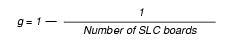
| • | Factor g for mobility within a CMI node: This thumb rule formula is based on the assumption of the mobility level of mobile subscribers. The factor g determines the probability that a station is not located at its home board when visiting the radio area of it home system. In the case of homogeneous allocation, the factor g can be calculated from the number of SLC boards in the system: |
|
| • | Factor G for mobility within the CMI network: This thumb rule formula is based on the assumption of the mobility level of mobile subscribers. The factor G determines the probability, that a subscriber resides outside the cordless area of his home system. In branch networks where subscribers rarely reside in other nodes, G is relatively small (e.g., G = 0.1). A homogeneous allocation can be assumed, if a location is overlapped from several cordless areas of different nodes. In this case, the factor G can be calculated from the number of CMI nodes: |

|
2.5.2.5 |
Current Thumb Rule Values |
| The following tables list the interfaces considered in the thumb rule formula with their respective meanings and corresponding weights in points (normalized to Anate seizures). |
| • | Table 2-35: Points for Devices |
| • | Table 2-36: Points for Mobile Handsets |
| • | Table 2-37: Points for Special Devices |
| • | Table 2-38: Points for Trunks |
| • | Table 2-39: Additional Overhead for Controlling Process Flows at Devices via CTI Applications |
| • | Table 2-40: Points for Groups |
Telephones |
Mobile Stations |
|
|
|
|
|
|
|
|
|
|
|
|
|
Special Devices |
|
|
|
|
|
|
|
|
|
|
|
|
|
|
|
|
|
|
|
Trunk Interfaces |
|
|
|
|
|
|
|
|
|
|
|
|
|
|
|
|
|
|
|
Additional Overhead for Features |
| The additional overhead values listed below are based on the assumption that the corresponding basic overhead for each terminal device involved has already been recorded in Table 2-35 . |
| |
|
|
|
|
|
|
|
|
|
|
| HiPath 3000/5000 V9, Service Documentation, Issue 10 | up  |
|
 |
||
| Disclaimer & Copyright | ID: P31003H3590S100017620 | 2014-02-27 |