|

|
4.2.4 |
Installing HiPath 3500 and HiPath 3300 (19-Inch Housing) |
| This section contains information on how to install the HiPath 3500 and HiPath 3300 19-inch housing. This chapter describes the standard installation procedures for the basic system. Refer to Chapter 9 "Expanding and Upgrading HiPath 3000" for information about supplementary equipment and expansions. |
4.2.4.1 |
Installation Versions |
| HiPath 3500 and HiPath 3300 are designed for the following types of installation: |
| • | Wall attachment (with assembly kit) |
| • | Desk installation (assembly kit includes adhesive feet) Stick the adhesive feet to the bottom of the housing. |
| • | Installation into 19" cabinet (with assembly kits for HiPath 3500 and HiPath 3300) |
| These systems also support the use of Powerbox PB3000. PB3000 can accommodate four batteries and/or an additional LUNA2 external power supply unit. The batteries guarantee uninterruptible power supply. LUNA2 is needed if the system's internal power supply unit is insufficient. Additional information can be found in Section 9.1.3 "Inserting Powerbox PB3000". |
4.2.4.2 |
Selecting the Installation Site |
Selecting a site |
| The customer usually has a preferred installation site in mind, for example an existing 19-inch cabinet. |
| Make sure that the customer's site meets the following guidelines: |
| • | To guarantee sufficient system ventilation, allow a minimum of 10 cm clearance around the housing. |
| • | Do not expose the systems to direct sources of heat (for example sunlight and heaters). |
| • | Do not expose the systems to extremely dusty environments. |
| • | Avoid contact with chemicals. |
| • | Take every precaution to prevent the formation of condensation on the system during operation. Systems covered with condensation must be dried before being used. |
| • | Observe the environmental conditions specified in Section 2.11 "Environmental Conditions". |
| Information on the design can be found in the following sections: |
| • | HiPath 3500 Section 2.1.4.4 "Design and Dimensions of HiPath 3500" |
| • | HiPath 3300 Section 2.1.4.5 "Design and Dimensions of HiPath 3300" |
4.2.4.2.1 |
For U.S. only: Power plug |
| The AC connection must fulfill the requirements specified in Table 4-13. |
| |
4.2.4.3 |
Unpacking the Components |
Procedure |
| |
|
4.2.4.4 |
Not for U.S.: Attaching a HiPath 3500 and HiPath 3300 to the Wall |
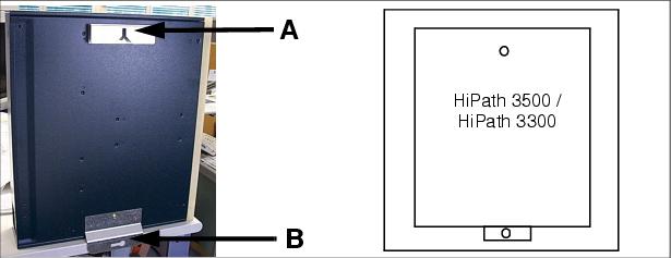
Procedure for wall mounting (Figure 4-62) |
|
Wall mounting |
4.2.4.5 |
Installing a HiPath 3500 or HiPath 3300 in a Cabinet |
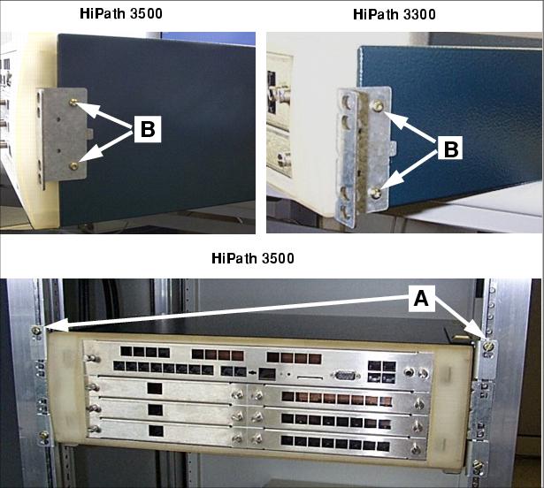
Procedure for 19-inch cabinets (Figure 4-63) |
|
Mounting the 19-inch cabinet |
4.2.4.6 |
Grounding the System |
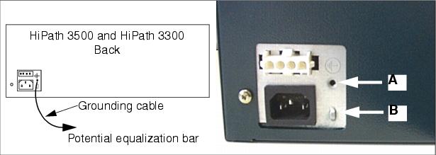
| Implementation guidelines in accordance with IEC 60364 and IEC 60950-1 must be adhered to during installation. |
Grounding: Inspection and Implementation |
|
||||||||||||||||||||||||||||||||||||
Procedure: Ground the system |
| Proceed as follows to ground the HiPath 3500 and HiPath 3300 systems (see also diagram below). |
|
|
4.2.4.7 |
Installing the Boards |
| The systems are already equipped with the boards needed for the customer's specific requirements. |
4.2.4.8 |
Connecting Cables and the Line Network |
Not for U.S. and Canada: PB3000 connection cable (if present) |
| To meet EMC requirements, the braided shields on the connection cable must be connected to the housing on both the HiPath 3500 or HiPath 3300 side and on the PB3000 side. |
| • | Attaching to the HiPath 3500 or HiPath 3300 side |
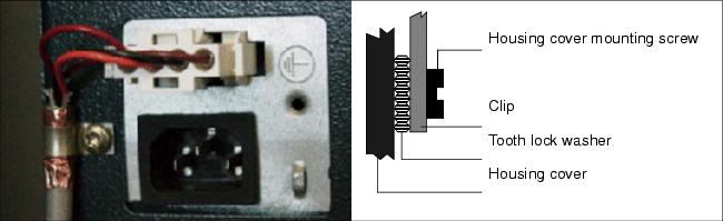
| Use a clip, a tooth lock washer, and a housing cover mounting screw to attach the braided shield to the HiPath 3500 or HiPath 3300 housing (as shown in Figure 4-65). The tooth lock washer must be mounted between the painted surface of the cover and the clip. |
| • | Attaching to the PB3000 side (see Section 9.1.3 "Inserting Powerbox PB3000") |
Line network |
| The connecting cords to the peripherals can be connected directly to the relevant MW8 jacks on the front panel of the 19-inch housing. |
Connecting the LAN cable for HXGR3 |
| LAN cables are connected to HXGR3 boards in a HiPath 3500 or HiPath 3300 according to the description in Section 3.3.4 "HXGS3, HXGR3". |
| • | Electromagnetic shielding |
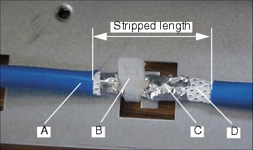
| To ensure sufficient electromagnetic shielding (according to EN 55022), a shielded LAN cable must be used, or the LAN cable being used must already be shielded. |
| • | Procedure: LAN cable shield contacts |
|
4.2.4.9 |
Configuration Notes |
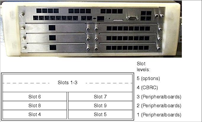
HiPath 3500: system overview and slots |
|
|
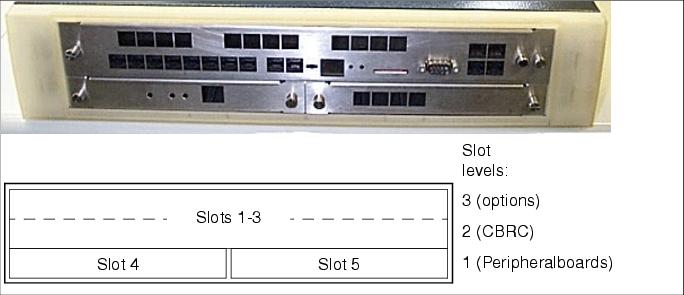
HiPath 3300: system overview and slots |
|
Static Traffic Capacity |
| The HiPath 3500 and HiPath 3300 systems have the following static traffic capacities. |
|
|
|
|
|
|
|
|
|
|
|
|
|
|
|
|
|
|
|
|
|
|
|
|
|
|
|
|
|
4.2.4.10 |
Connecting Workpoint Clients |
| For information, see Chapter 10 "Workpoint Clients". |
4.2.4.11 |
Making Trunk Connections |
| Refer to the following board descriptions for information: |
| • | STLS4R (S0 trunk connection) |
| • | TS2R, only HiPath 3500 (S2M trunk connection) |
| • | TLA4R (not for U.S.) (MSI) |
| • | TMGL4R (for U.S. only) |
| • | TST1 (for U.S. only), HiPath 3500 only |
4.2.4.12 |
Performing a Visual Inspection |
| Before starting up the system, you must perform a visual inspection of the hardware, cables, and the power supply. The visual inspection must be performed while the system is disconnected from the power supply. |
|
| |
|
4.2.4.13 |
Installing the EXMR on the CBRC |
| This section describes the installation of the external music module EXMR S30122-K7403-T-* on the main board CBRC (S30810-K2935-Z401-*) of the HiPath 3300/3500 system. |
| The following points must be observed when installing the EXMR: |
| • | Implementation guidelines in accordance with EN 60950 |
| • | The installation should be performed only by authorized service personnel. |
| • | Before the installation, the HiPath system must be be switched off and disconnected from the power supply. |
| To install the EXMR, proceed as follows: |
| 1. | Insert the RCA jacks of the supplied NF audio cable on the right side of the front panel of the CBRC module. |
| 2. | Insert the two wires at the other end of the NF audio cable into the 2-pole Wieland connector and tighten the connection. Then plug in the Wieland connector on the EXMR module. |
| Due to the galvanic isolation on the EXMR module, the wires are interchangeable. |
| 3. | Attach the NF audio cable with a cable tie to the EXMR module. The cable tie should not touch the components of the EXMR module! |

|
| Figure 4-68 | Front view of EXMR module with the cable ties
|
| 4. | Insert the EXMR module with the component side down into the 6-pin X19 and X20 ports of the CBRC. |

|
| Figure 4-69 | Rear view of EXMR module mounted on the CBRC
|
| HiPath 3000/5000 V9, Service Documentation, Issue 10 | up  |
|
|
||
| Disclaimer & Copyright | ID: P31003H3590S100017620 | 2014-02-27 |