3.3.38  

TMCAS-2 (for selected countries only) 
 
NOTE  
Danger of damage to property due to surge voltage. The required lightning protection measures must be taken for this board, see Section 2.1.2 "Lightning Protection".  

Introduction  
The TMCAS-2 card (Trunk Module Channel Associated Signaling) can be used in HiPath 3800 for V5.0 SMR-10 and later to support country-specific CAS protocols.
The card features two E1-CAS interfaces, which together support up to 60 B channels.
Both coaxial trunks (75 ohms) and symmetrical trunks (120 ohms) can be connected to the 15-pin sub-D jacks on the card.
TMCAS-2 functions as a converter, which converts the Euro-ISDN protocol on an S2M link to the Channel Associated Signaling (CAS) protocol. In contrast to the predecessor PBXXX card, TMCAS-2 communicates directly with the central control in the system. All signaling and data traffic goes through TMCAS-2. Unlike PBXXX, a connection with an S2M card is therefore not required.
Up to three TMCAS-2 cards can be used in a HiPath 3800.
 Figure 3-103   TMCAS-2 (S30810-Q2946-X) (for selected countries only) - Figure
 

Interfaces and Jumpers  
 Figure 3-104   TMCAS-2 (for selected countries only) - Interfaces and Jumpers
 

Settings  

 Table 3-146   TMCAS-2 (for selected countries only) - Jumper Functions
 Jumper  
 Function  
 Setting  
 Pins 1-2 closed  
 Pins 2-3 closed  
 X11  
 Sets the V.24 baud rate  
 See Table 3-147  
 X12  
 X14  
 X13  
 Deletes the flash memory  
 Flash memory is deleted (all sectors apart from U-boot (firmware)).  
 Flash memory is not deleted.  
 (default setting)  
 X16  
 Resetting the card  
 Reset performed.  
 Reset not performed.  
 (default setting)  
 X17  
 Hardware watchdog  
 Watchdog active.  
 (default setting)  
 Watchdog not active.  
 X24  
 Sets trunk impedance for CAS interface 1  
 75 ohms  
 (default setting)  
 120 ohms  
 X25  
 Sets trunk impedance for CAS interface 2  
 75 ohms  
 (default setting)  
 120 ohms  
 X999  
 Grounding: card / CAS cable  
 Grounding for the card is connected to the grounding for the CAS cable.  
 Grounding for the card is not connected to the grounding for the CAS cable.  
 (default setting)  

 Table 3-147   TMCAS-2 (for selected countries only) - Jumper for Setting the V.24 Baud Rate
 V.24 baud rate
(Kbps)  
 Jumper  
 X11  
 X12  
 X14  
 9.6  
 (default setting)  
 Open  
 Open  
 Open  
 19.2  
 Open  
 Open  
 Closed  
 38.4  
 Closed  
 Open  
 Closed  
 57.6  
 Open  
 Closed  
 Closed  
 115.2  
 Closed  
 Closed  
 Closed  
 9.6  
 All other configurations  

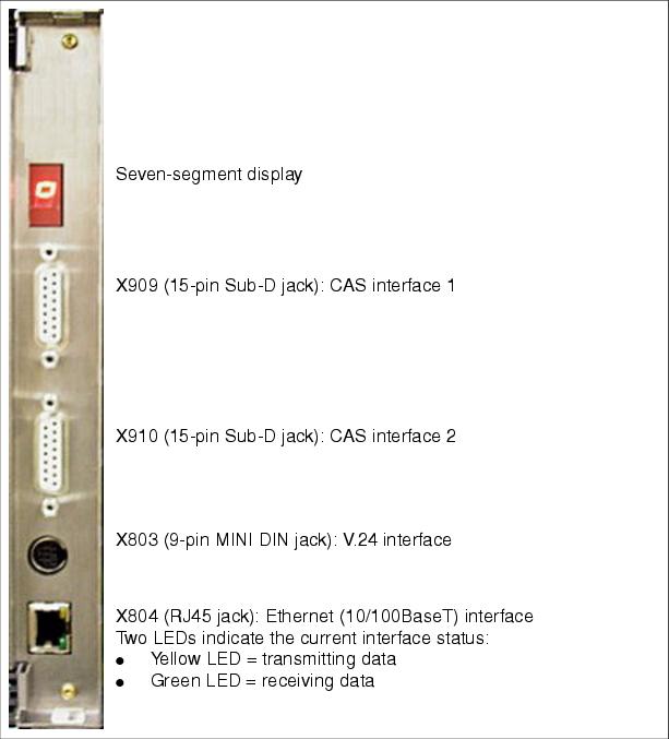
Front panel  
 Figure 3-105   TMCAS-2 (for selected countries only) - Front Panel
 
An additional shielding panel is not required on the front side of this board, because the EMC shield is already provided by the front panel.

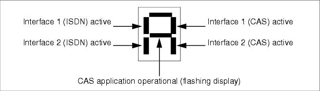
Seven-segment display  
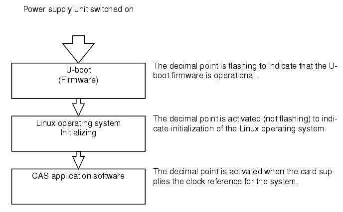
The card's software status can be ascertained on the basis of the seven-segment display. For this a distinction is made between the following boot phases:
 •   U-boot (firmware) states
   
 Table 3-148   TMCAS-2 (for selected countries only) - U-boot (firmware) States
 Display  
 Meaning  
 
Initializing hardware  
Downloading DSP (Digital Signal Processor) firmware  
Downloading FPGA (Field Programmable Gate Array) firmware  
 
Accessing flash EPROM (Save and Delete)  
 
Activating built-in self test BIST (BIST1 or BIST2)  
 
Administration (Service PC connected)  
 
Copying software (from SDRAM to FEPROM)  
 
Downloading image file (Linux and CAS application)  
 
Initializing the Linux operating system  
 
Error  
 
Resetting the card  
 
U-boot (firmware) operational (decimal point flashing)  
 •   Linux operating system states
   
 Table 3-149   TMCAS-2 (for selected countries only) - Linux Operating System States
 Display  
 Meaning  
 
Linux kernel boot  
 
User space boot  
 
Check and mount flash  
 
Error found, mounted file system rebuild, reboot  
 
Mounting flash file system  
 
Error mounting flash (flashing display)  
 
Configuring network interface  
 
Loading real-time kernel modules  
 
Loading board-specific modules  
 
Core files available  
 •   CAS application software states
   
   Figure 3-106   TMCAS-2 (for selected countries only) - CAS Application Software States
 

Modem (optional)  
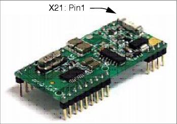
 Figure 3-107   TMCAS-2 (for selected countries only) - Optional Modem
 
The analog modem (S30122-X8004-X22) is an optional subboard for the TMCAS-2 card, which is plugged into the X20 and X21 ports. This facilitates remote administration of the CAS protocol converter on the TMCAS-2 card (see Seite 3-312).

Administration of the CAS protocol converter  
A separate tool, the CAS Manager, is used to download the software and administer the TMCAS-2. The CAS Manager software is stored on a CD supplied with the card. For information on how to install the CAS Manager software on the Service PC, refer to the readme file.
The following options are available for accessing the card:
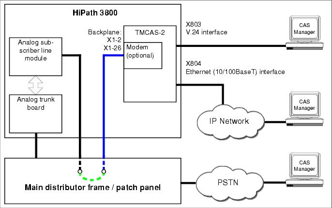
 •   Via the V.24 interface (9-pin MINI DIN jack X803) and the connection cable C39195-A9700-B532.
 •   Via the Ethernet (10/100BaseT) interface (RJ45 jack X804).
 •   Via the optional analog modem (S30122-X8004-X22). In this case, you will need to establish a connection from the analog modem to a free port on an analog subscriber line module. Use a connection cable (open-end cable (24 DA)) for the connection Backplane (TMCAS-2) <-> Main distribution frame/Patch panel: Use S30267-Z196-A150 = 15 m in length, S30267-Z196-A250 = 25 m in length) (blue in Figure 3-108). Insert the required jumpers in the main distributor frame or patch panel (green in Figure 3-108).
 Figure 3-108   TMCAS-2 (for selected countries only) - Connection Options for Card Administration using CAS Manager
 

Assigning both CAS cables  
You can use one of the following two cables to connect network terminators (NT), multiplexers (MUX), or modems to the TMCAS-2 card (15-pin sub-D jacks X909 and X910):
 •   symmetrical line (120 ohms), length = 10 m
   
 Table 3-150   TMCAS-2 (for selected countries only) - Assignment of the CAS Cable S30267-Z167-A100
 15-pin Sub-D connector  
 Pin  
 Function  
 Color code  
 9  
 a-wire (T), transmit  
 wht/blu  
 1  
 b-wire (R), transmit  
 blu/wht  
 15  
 a-wire (T), receive  
 wht/ora  
 8  
 b-wire (R), receive  
 ora/wht  
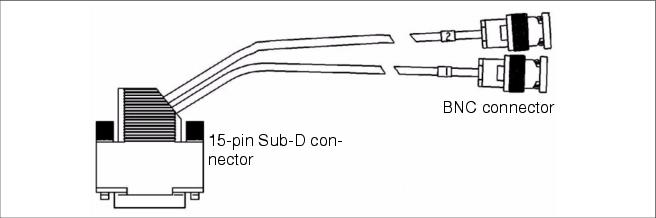
 •   Coaxial trunk (75 ohms), length = 10 m
   
 Table 3-151   TMCAS-2 (for selected countries only) - Assignment of the CAS Cable C39195-A7700-B14
 Wire  
 Function  
 15-pin Sub-D connector  
 Pin  
 BNC connector  
  1  
 Receive, Tip  
 8  
 Shield  
 Receive, Ring  
 15  
 Conductor  
 2  
 Transmit, Tip  
 1  
 Shield  
 Transmit, Ring  
 9  
 Conductor  
   
   Figure 3-109   TMCAS-2 (for selected countries only) - CAS Cable C39195-A7700-B14