|
|
|

|
3.3.23 |
STLS2 (not for U.S.), STLS4 |
|
Introduction |
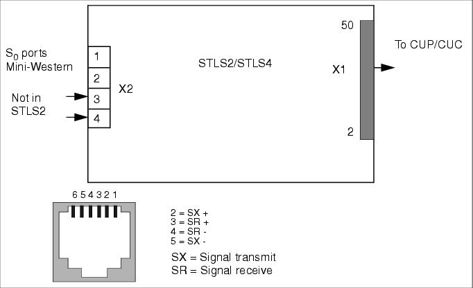
| The STLS4 board for HiPath 3550 and HiPath 3350 (wall housing) has four S0 ports that can operate as trunk interfaces or as subscriber line interfaces (see Seite 3-223). |
| The STLS2 is an underequipped variant with two S0 ports. |
Interfaces |
|
Interface Assignments (for U.S. only) |
| |
| Note: The STLS4 module supports the trunk side in Europe, so the transmit and receive signals must be reversed before the first device on the S0 bus. |
| The ISDN terminals must have their own local power supply. |
| The system assigns the MSN only after the S0 port is configured on the "Euro bus" (not for U.S.) and can be read out via the administration (Assistant T: Code 20 4 3 S0-Bus MSN). |
Connecting ISDN (S0) interfaces (not for U.S.) |
| You can use the MW jacks on the STLS boards to connect between one and four ISDN S0 buses. The interfaces on the STLS boards are freely configurable. |
| • | EURO CO point-to-point |
| • | EURO CO point-to-multipoint |
| • | EURO bus |
| • | CorNet N/CorNet NQ slave |
| • | Using HiPath 3000/5000 Manager E, you can also set up configurations for networking and dedicated lines |
| Use the S0 interface S01 for connection to the public telecommunications network (ISDN trunk). |
| You can also connect S0 interfaces S02 to S04 to the ISDN trunk or to ISDN terminals (ISDN telephone, group 0 fax device, PC, dialing aid) via an S4 bus. |
| The connection (networking) to HiPath 3000 and HiPath 4000 (CorNet NQ) can also be set up via S0 interfaces S01 to S04. |
| S0 connection options: |
| • | Point-to-point (PP) (default) |
| • | Point-to-multipoint (PMP) |
Connecting an ISDN trunk (not for U.S.) |
| Insert the connection cable supplied in jacks S01 to S04. Insert the other end in the NT of the carrier. |
Networking connection (HiPath 4000/CorNet NQ (not for U.S.) |
| Insert the connection cable supplied in jacks S01 to S04. Connect the other end with the HiPath 4000 port. |
Connecting ISDN terminals (not for U.S.) |
| Depending on the system, you can set up a maximum of four internal S0 buses (S0 1 to S0 4). A maximum of eight ISDN terminals can be addressed on each S0 bus. |
| The system does not assign the MSN until the S0 port is configured on the "EURO bus"; the MSN can be read out via administration. |
| When you set up an S0 bus, it is assigned an MSN. This MSN is the first free station number in the system. The S0 station is immediately available under this MSN, without an outgoing seizure. |
|
Configuring an S0 bus with a Mini-Western jack (not for U.S.) |
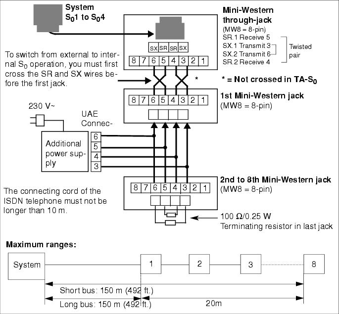
| S0 telephones cannot be directly connected to an STLS board's Mini-Western jack via the cable supplied. You must first install a jack with cross-connected cables (see Figure 3-71). |
Connecting ISDN Terminals to HiPath 3550 and HiPath 3350 (for U.S. only) |
| • | S0 Bus With MW8 jack, connecting S01 to S04: |
| - | Connect the provided, silver-satin connector cord to each port on the STLS4 Module. Connect the other end to a mounted MW jack, reversing the transmit and receive wires. |
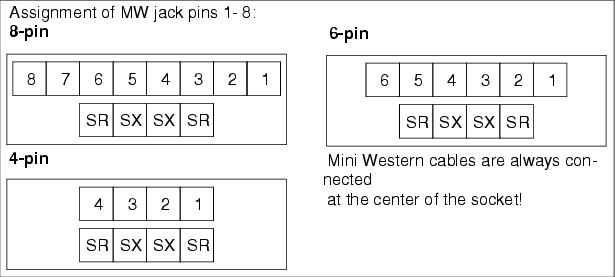
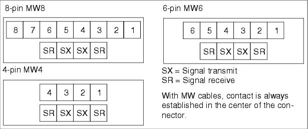
| - | Contact is always established using the center pins of MW jacks. Figure 3-72 shows the pin assignments for jacks of different sizes. |
| - | The ISDN terminals must have their own local power supply. |
| - | Plug the ISDN terminal (connecting cord) into the MW jack. Connecting an ISDN S0 telephone requires a local power supply (e.g. manufactured by Sedlbauer). |
| • | Pin Assignment of MW Jacks |
| HiPath 3000/5000 V9, Service Documentation, Issue 10 | up  |
|
|
||
| Disclaimer & Copyright | ID: P31003H3590S100017620 | 2014-02-27 |