3.3.12  

SLAD16 
 
NOTE  
Danger of damage to property due to surge voltage. The required lightning protection measures must be taken for this board, see Section 2.1.2 "Lightning Protection".  

Introduction  
HiPath 3000/5000 V7 R6 or later supports the use of the SLAD16 board (Subscriber Line Analog with DuSLIC) in HiPath 3550 and HiPath 3350 to connect analog stations (analog telephones, Group 3 fax devices, etc.).
The SLAD16 board (S30810-Q2957-X) is the compatible successor module for the 16SLA (S30810-Q2923-X) board. This is being discontinued and can no longer be ordered.

Main features  
A DTMF code receiver is available for each analog interface (permits DTMF dialing at analog telephones). This guarantees that all analog terminals connected are fully accessible.
These boards support calling name identification presentation (CLIP).
It is prohibited to connect external extensions to SLAD16 using OPS signaling (off-premises station).
Ring voltage is generated by the UPSC-D power supply unit and may require connection to an external power supply unit depending on configuration. Please refer to Section 2.8 "Country-Specific Ring Frequencies for Analog Subscriber Line Modules" for information on how to set the country-specific ring frequency.

Configuration rules for HiPath 3350  
The following rules must be observed when using an SLAD16 board to guarantee that the communication system is sufficiently cooled:
 •   The second HiPath 3350 slot may not be occupied with the following boards: SLAD16, SLAD8, SLAD4, 16SLA, 8SLA, 4SLA.
 •   Up to 20 analog stations may be connected to HiPath 3350 (including CBCC).

Configuration rules for HiPath 3550  
The following table provides which slots have to be used by SLAD16 boards in which sequence depending on the number of analog station ports which have to be realized; and it provides if the fan kit C39165-A7021-B46-1 and/or the Power Box PB3000 have to be assembled. It depends on the number of SLAD16 boards and the loop current which was set if the fan kit and/or the Power Box have to be used.
The Power Box PB3000 (or another additional power supply) is always required if the UPSC-D does not deliver sufficient capacity for the number of the connected devices. This depends on the preset supply current and can apply for less than 32 devices which are connected to the SLAD16 boards. The installer is responsible for the correct configuration. The calculation of the required power is described in section "D.2 HiPath 3550 Board Power Requirement".
The sequence of using the slots by SLAD16 boards - i. e. 6, 8, 4 and 7 - which is provided in the table has to be implicitly observed. Slots which are not occupied by SLAD16 boards can be used by other boards.
The ambient temperature has to amount between 5°C (41°F) and 40°C (104°F).

 Tabelle 3-58   Decision array for HiPath 3550: Assembly of fan kit and Power Box
CBCC (4 a/b ports,  
8 UP0E ports)  
 Slot  
 Loop current  
 Fan kit  
 Power Box  
Number of analog ports (Number of SLAD16)  
 6  
  8  
  4  
  7  
 20.5 mA  
 23.2 mA  
 28.2 mA  
 33.2 mA  
 36.5 mA  
 required
Yes/No
 
16 (1 SLAD16)  
 X  


 X  


 No  
 No  
16 (1 SLAD16)  
 X  


 X  


 No  
 No  
16 (1 SLAD16)  
 X  


 X  
   
   
 No  
 No  
16 (1 SLAD16)  
 X  


 X  
   
 No  
 No  
16 (1 SLAD16)  
 X  


 X  
 No  
 No  
32 (2 SLAD16)  
 X  
 X  
   
   
 X  


 No  
 No  
32 (2 SLAD16)  
 X  
 X  


 X  


 No  
 No  
32 (2 SLAD16)  
 X  
 X  


 X  
   
   
 No  
 Yes  
32 (2 SLAD16)  
 X  
 X  


 X  
   
 No  
 Yes  
32 (2 SLAD16)  
 X  
 X  


 X  
 Yes  
 Yes  
48 (3 SLAD16)  
 X  
 X  
 X  
   
 X  


 No  
 Yes  
48 (3 SLAD16)  
 X  
 X  
 X  
   
   
 X  


 No  
 Yes  
48 (3 SLAD16)  
 X  
 X  
 X  


 X  
   
   
 Yes  
 Yes  
48 (3 SLAD16)  
 X  
 X  
 X  


 X  
   
 Yes  
 Yes  
64 (4 SLAD16)  
 X  
 X  
 X  
 X  
 X  


 No  
 Yes  
64 (4 SLAD16)  
 X  
 X  
 X  
 X  
   
 X  


 No  
 Yes  
64 (4 SLAD16)  
 X  
 X  
 X  
 X  
   
   
 X  
   
   
 Yes  
 Yes  
64 (4 SLAD16)  
 X  
 X  
 X  
 X  


 X  
   
 Yes  
 Yes  
NOTE  
The fan kit (C39165-A7021-B46-1) is not permitted in the U.S. and Canada; therefore, only configurations without fan kit can be used in these countries.  

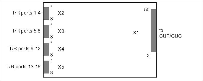
Interfaces  
 Figure 3-50   SLAD16 - Interfaces
 

 Table 3-59   SLAD16 - Port Assignment
 X2, Pin  
 T/R ports
1-4  
 X3, Pin  
 T/R ports
5-8  
 X4, Pin  
 T/R ports
9-12  
 X5, pin  
 T/R ports
13-16  
 1  
 a 1  
 1  
 a 5  
 1  
 a 9  
 1  
 a 13  
 2  
 b 1  
 2  
 b 5  
 2  
 b 9  
 2  
 b 13  
 3  
 a 2  
 3  
 a 6  
 3  
 a 10  
 3  
 a 14  
 4  
 b 2  
 4  
 b 6  
 4  
 b 10  
 4  
 b 14  
 5  
 a 3  
 5  
 a 7  
 5  
 a 11  
 5  
 a 15  
 6  
 b 3  
 6  
 b 7  
 6  
 b 11  
 6  
 b 15  
 7  
 a 4  
 7  
 a 8  
 7  
 a 12  
 7  
 a 16  
 8  
 b 4  
 8  
 b 8  
 8  
 b 12  
 8  
 b 16  

Installing fan kit C39165-A7021-B46-1 for SLAD16 in HiPath 3550  
NOTE  
Installing the fan kit marks the end of silent system operation. This must be taken into consideration when operating the system in an office environment.  
To install and connect the fan kit, proceed as follows:

 Step  
 Activity  
 1.  
   
Disconnect system from power supply.  
CAUTION  
Risk of electric shock through contact with live wires  
Always switch off the system voltage by plugging the power plug out. If using an uninterruptible power supply (USP) on the system, switch off the battery voltage first.  
 2.  
   
Open the system.  
CAUTION  
Cuts caused by sharp edges on the shielding plate  
When opening the system, ensure that you only touch the housing cover from the outside (see Section 4.2.3.4 "Removing the System Housing Cover").  
 3.  
Place the fan kit [A] on the system's shelf [B]
(see Figure 3-51).  
 4.  
   
   
 NOTE:  
Arrange all fan kits on the board frame so that cool air reaches all expansion slots, i.e., the distance [C] to the wall must be approx. 45 mm, (see Figure 3-51).  
Danger of overheating from incorrect positioning of the fan kit
The fan kit should not be mounted directly above the baseplate because in this position the cool air does not reach all the expansion slots!  
 5.  
Push the two supplied securing clips over positions [D] illustrated in Figure 3-51 to attach the fan kit to the shelf.  
 6.  
Remove the power supply cable between PB3000 and UPSC-D and replace it with the new power supply cable C39195-A7985-B41-1. This cable has a branch-off point for the fan kit.  
 7.  
Place the connection cable [E] for the fan kit on the shelf as displayed in figure Figure 3-52 and attach them with cable ties [F] at the points shown.  
 8.  
Close the plug connection [G] to connect the fan kit connection cable and the branched part of the power supply cable
(see Figure 3-53).  
 9.  
Close the system.  
CAUTION  
Cuts caused by sharp edges on the shielding plate  
When opening the system, ensure that you only touch the housing cover from the outside.  
 10.  
Start the system by plugging in the power plug. If using a UPS, the battery voltage must also be switched on.  
 Figure 3-51   SLAD16 - Installation of the Fan Kit in HiPath 3550
 
 Figure 3-52   SLAD16 - Fan Kit Connection Cable
 
 Figure 3-53   SLAD16 - Connection of the Fan Kit